

Choosing the Correct Speed Mitigation Device
When a vehicle is forced to vertically deflect, the driver and passengers feel discomfort. As the deflection is occurring in the vertical direction, and the rate of vertical acceleration is higher at higher speeds, drivers are strongly motivated to slow down while crossing. The effectiveness of the vertical deflection in slowing down traffic makes the four types of such devices – speed bumps, speed humps, speed cushions, and speed tables – one of the most common traffic calming measures used globally.
The four different traffic calming types above are vertical deflection types that have differing shapes and are highly effective in slowing down traffic. Each of the four is three-dimensional objects with specific dimensions that result in different rates of vertical acceleration in a vehicle driving over them. This article is set to offer comprehensive information regarding the most common and effective speed mitigation devices above. It would present the correct height and length for each, their primary areas of application, and a few tips for their effective use. In addition, the article would be using information from the Institute of Transportation Engineers (ITE) standards, as well as data from other popular resources such as the American Association of State Highway and Transportation Officials (AASHTO), the Federal Highway Administration (FHWA), and the UK Department for Transport (UK DoT).
Section 1: Speed bumps
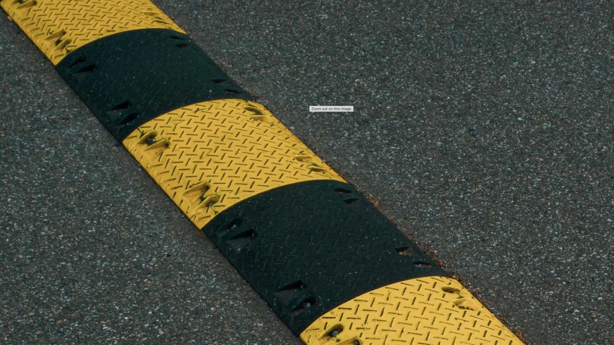
A speed bump is the most common type of vertical deflection speed mitigation device. Speed bumps are raised objects with an abrupt profile that have a very small travel length, which can be as small as 1 foot. Speed bumps can be extremely small structures with a height of between 3 and 6 inches, which is in the range of 76-152 mm. Travel length is the distance covered by the structure in the direction of traffic flow.
Speed bumps are more or less uniform. They are extremely short and therefore present a vertical wall-like structure to the vehicle passing over them. Speed bumps tend to produce very high acceleration levels at very low speeds and create a major comfort problem. It is for this reason that they are not standard like the speed hump. Speed bumps are not designed and not standardized and do not have a specific design speed. In fact, according to ITE guidelines on traffic calming, speed bumps have no standard design speed, and most of them are implemented with less consideration on the typical design factors.
Speed bumps have been used to raise vertical acceleration in the driver or vehicle occupants. As per information from different sources, speed bumps tend to produce vertical accelerations in the range of 0.8 to 1 g while a vehicle’s speed is 5 to 10 mph. A speed bump would usually be constructed on a private property or in private property. According to FHWA and the DoT, speed bumps are not recommended on public highways due to the high potential for accidents when not done correctly and the need for speed levels to be very low.
Section 2: Speed Humps
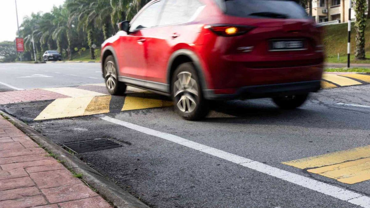
Speed humps were one of the traffic calming structures that have gone through a lot of research and therefore more of a well-thought-out structure. They were a design improvement over the crude speed bump. They are the most studied type of vertical deflection device and were the result of a lot of years of research into different traffic calming structures. According to the ITE standards, a speed hump is a vertical deflection device that is constructed in the direction of traffic flow at a speed of between 12 ft and 3.66 m long and is 3 to 4 inches in height, which is equivalent to 76-102 mm. Speed humps usually have a parabolic, sinusoidal, or circular profile that makes their effectiveness much better than the crude speed bump.
Studies of traffic calming devices by different authors show that speed humps have reduced speeds by between 6 and 13 mph. This is data from the FHWA, which has information collated from seven different field studies of 199 speed humps. The ITE has recommended a standard 12-ft parabolic hump, which it says can help the 85th percentile speed to reduce to an equivalent speed range of between 15 and 20 mph, which is the speed range of 24 to 32 km/h.
Vehicle dynamics of speed humps are different from those of speed bumps, due to the increased length of a hump. Longer length allows the vehicle’s suspension system more time to respond to the vertical deflection and so slow the rise in vertical acceleration. For speeds that are above the design speed of the speed hump, vehicle occupants start to experience the vertical acceleration as uncomfortable, and therefore, the driver tries to reduce speed. For example, research conducted by different authors has shown that a sinusoidal profile of speed humps will produce a peak vertical force of about 3,500 Newtons. The research further indicates that a flat-topped bump will lead to a vertical force of about 6,000 Newtons, which is about 70% more than that produced by a sinusoidal profile. This is a big difference in vertical forces and will ultimately be very uncomfortable for the vehicle occupants.
The AASHTO has also come out with design standards for a speed hump. The AASHTO standards are that speed humps should be clearly visible from a distance of at least 75 m or 250 feet, which will help the driver to identify it earlier enough and give them enough time to slow down their vehicle if the speed is higher than the design speed. The standards are also clear that a speed hump should not be installed on a horizontal curve with a radius of less than 90 m or 300 feet. Horizontal curves tend to create a situation where there will be both vertical and lateral accelerations.
Speed humps are best implemented on roads such as residential streets or any other street that has a speed limit of 30 mph or less. For them to be very effective, they are best implemented on a two-lane road or a narrower road where traffic volume is low to moderate. Studies have also shown that the speed levels between speed humps will be higher by about 0.8 km/h for every 30 m distance between two humps. Using this relationship, a traffic engineer can calculate how the spacing of the humps will affect the speeds of a vehicle between two speed humps.
Section 3: Speed Cushions
Speed cushions are one of the most recent developments in the improvement of traffic calming structures. Speed cushions can be described as an evolved version of the speed hump. This means that speed cushions tend to share many of the same characteristics with a speed hump.
The main difference between speed cushions and speed humps is in the profile. Speed cushions have gaps, or cutouts, between raised elements on the cushion. The individual raised elements tend to have the same dimensions that the speed hump has. In other words, a raised element on a speed cushion will tend to be about 12 feet in the direction of traffic flow and have a height of 3 to 4 inches. The cushion’s lateral gaps are, however, specifically sized for emergency and transit vehicles to have a wide enough track width to pass over them with little to no deflection. This means that the typical car will have to place the centre of its wheels over the raised element on the speed cushion. As per information from different authors, cars have a narrow track width and so tend to be deflected as their wheels are over the raised element on the speed cushion.
The cushion allows fire engines and ambulances to pass without being deflected as they are wide enough to pass between the raised elements on the speed cushion. The typical vehicle with narrow track widths will have a problem passing a speed cushion without a vehicle dynamic deflection. Studies that have been conducted on speed cushions have shown that vehicle speeds can be significantly reduced as per different authors, who have information collated from two field studies of three speed cushions. The information from these studies shows that the speed cushions can help reduce the 85th percentile speed by between 5 and 7 mph.
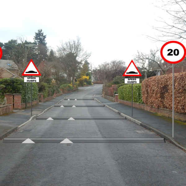
Vehicle dynamics of the speed cushion are the same as those for a speed hump as long as the vehicle will drive over the middle of the speed cushion. However, if the vehicle driver decides to attempt to pass over the speed cushion by straddling it or passes over it off-centre, it will experience an asymmetrical loading situation. This is going to make it even more uncomfortable for the vehicle occupants. The UK DoT has given some useful information on the subject of speed cushions that have been developed for 20 mph zones in the UK. The British have very strict standards on speed cushions. They have set the following parameters as the design standards for speed cushions. These standards are 550 mm wide, 450 mm wide gaps, and 1500 mm spacing. The study that has been done has shown that these designs tend to allow fire engines to pass over the speed cushion at a speed range of 20 to 25 mph and vehicles to slow down to a speed range of 15 to 20 mph.
Speed cushions have found their applications in locations such as roads that are used by emergency services, for example, for access to a fire station. They can also be used on roads that have regular bus service. They have also been used in residential streets where there is a need for emergency vehicles to pass without experiencing a great deal of delay.
Section 4: Speed Tables
Speed tables are three-dimensional vertical deflection traffic calming structures that have seen very many changes in design over time. Speed tables are very wide and come in different lengths that can affect their design speed. Speed tables are the longest of the vertical deflection types. As per information from different authors and standards, speed tables can have a length of between 10 to 30 ft or 3.05 to 9.14 m in the direction of traffic flow. Speed tables also have a height of between 3 to 6 inches, which is equivalent to 76-152 mm. In a standard design, speed tables usually have a parabolic profile but they can have different profiles such as flat-top or sinusoidal. The following sections are about to look at the differences in the shape of speed tables, for example, the differences between a flat-top and a parabolic speed table. It will also look at the implications of the profiles on the effectiveness of the traffic calming structure.
This traffic calming device has a vehicle speed reduction of between 4 and 9 mph at the 85th percentile speed. This is data collated by the FHWA that is from three field studies of 57 speed tables. The ITE recommends the use of a standard 20 ft speed table for design purposes. The standard 20-ft speed table is recommended because the 85th percentile speed of vehicles will be at a speed range of 15-20 mph, which is equivalent to a speed range of 24-32 km/h. Vehicle dynamics of the flat-top speed table are the same as that of the parabolic speed table as long as the vehicle passes over the centre of the speed table. If it is not in the centre, it will create a situation where there will be an asymmetrical loading situation, which is not comfortable for the vehicle occupants.
The FHWA recommends the use of the speed tables in the following places. They have indicated that speed tables should be implemented where speeds can be low enough to allow a driver to cross an intersection, stop or yield. Speed tables can be implemented where there is a need to provide a level crossing facility at intersections to cyclists and pedestrians. They have also indicated that speed tables can be used on a through road where the speed limit is above 20 mph. Speed tables are said to be very effective when they are used on arterial streets or collector roads.
This article has offered some useful and complete information on speed bumps, speed humps, speed cushions, and speed tables. It has explained some of the most vital information about these structures and the fundamental physics of their workings. These are the four of the most important and widely used types of vertical deflection traffic calming structures.
Speed tables, sometimes referred to as trapezoidal humps, plateaus or raised crosswalks, are the most complex and driver-friendly type of vertical deflection device. Speed tables are characterised by a flat top where the entire wheelbase of the vehicle sits. In contrast, speed bumps and speed humps have a peaked profile where only the leading or trailing wheels sit on the deflection device. Institute of Transportation Engineers specifications have led most agencies to implement speed tables with heights of 3 to 3.5 inches (76-90 mm) and a total travel length of 22 feet (6.7 m), with a typical profile of 10 feet (3.1 m) of plateau and 6 foot (1.8 m) approach and departure ramps on both sides. Approaches can be straight, parabolic or sinusoidal profile; each geometry has ride and speed reduction performance differences.
The extended travel length of a speed table changes the vehicle dynamics fundamentally from shorter humps. As the vehicle moves onto the approach ramp, the front suspension compresses which pitches the vehicle upward. However, prior to the rear wheels reaching the approach ramp, the front wheels arrive at the flat plateau and the front suspension extends. The full vehicle sits flat on the plateau with very little pitch angle for a short distance. This device geometry delivers a much smoother ride than a speed hump. The vehicle pitch angle is smaller, and the vertical acceleration consists of two distinct phases (acceleration and deceleration) separated by a level travel period. Studies have shown that the design of this profile can accommodate vehicles to comfortably traverse speed tables at speeds of 20-25 mph (32-40 km/h). This allows for speed tables to be used on roads with higher design speeds than speed humps.
The UK has produced some of the most comprehensive and detailed specifications for speed tables through the Department for Transport’s Local Transport Note 1/07. Plateaus created by ramps rising 75 mm at a 1-in-12 gradient (approximately 8.3%). The plateau itself is typically 7 metres long for most applications but 12 metres long for public transport routes with a gentler 1-in-15 gradient (approximately 6.7%). The reduced gradient and increased plateau length on public transport routes are to minimise passenger discomfort.
UK data from the Transport Research Laboratory Report 186 shows the following;
“The mean speeds recorded by TRL of motor vehicles when crossing speed tables were about 13 mph (21 km/h), with speeds in between speed tables on 84 m spacings about 20 mph (32 km/h). This data shows the importance of sufficient spacing to retain the reduced speed along an entire length”
Vertical deflection treatments are expected to reduce accidents by 44%. This is a significant safety improvement to consider in the cost benefit calculation.
Speed tables have a variety of different uses on the road network. Raised crosswalks are the most pedestrian-focused application, where the entire crosswalk is raised to pavement level. Raised pedestrian crosswalks improve visibility for pedestrians, reduce physical effort to step up onto the road, and naturally calm traffic. Raised crosswalks are also often applied at junction treatments, where the speed table reduces vehicle speeds and adds extra prominence to the intersection. Their smoother profile allows them to be used on roads with design speeds up to 35 mph in some cases, opening the door to traffic calming effects on collector roads and minor arterials where speed humps would be too aggressive.
An important nuance to speed table applications is the accessibility factor. The flat top and less aggressive approach ramps are generally preferred by drivers with disabilities and wheelchair users. Speed tables used as raised crosswalks remove the need for kerb ramps, providing a level crossing surface for all pedestrians, and greatly benefit those using mobility scooters, pushchairs, or wheeled luggage.
Section 5: Comparative Vehicle Dynamics and Physics
The physics that make vertical deflection devices work is the same for all three types of vertical deflection devices. The only differences are severity, compliance with standards, and geometry. All deflection devices utilise the vertical displacement relationship between vehicle speed and occupant comfort. As a vehicle rolls over a raised surface, the wheel must follow the deflection contour, causing the body to experience vertical acceleration. Vertical acceleration propagates through the vehicle suspension system and chassis to the vehicle occupants. The rate of vertical acceleration experienced is proportional to three primary factors: the vertical height of the deflection, the length of travel over which the deflection occurs (approach angle), and the vehicle speed. This relationship is exponential; doubling the speed over a given bump geometry quadruples the resultant vertical acceleration. It is this exponential increase in harshness that acts as the enforcement mechanism.
Early research into the dynamics of vertical deflection devices found that peak vertical acceleration occurs in the first half of the bump as the wheels first hit the rising surface. The vehicle suspension system must react as quickly as possible to fully extend the suspension travel and absorb the full deflection height. This rate of extension is determined by the suspension spring rate and damper settings, but all suspension systems have finite rates of extension/compression. If the vehicle speed is too high for the suspension system to fully extend, the harshness of impact from exceeding the suspension travel is transferred directly to the chassis.
Vehicle suspension systems have a range of parameters that differ based on make, model and design intent. For example, luxury saloons will have soft suspension and high suspension travel which are optimised to absorb bumps but this is in stark contrast to sports cars with stiff suspension and low suspension travel optimised for performance driving. Both vehicle types will experience great discomfort on an aggressive speed bump, even at inappropriate speeds. Vehicle suspension systems will only do so much to reduce the discomfort from vertical deflection devices – once speed limits are exceeded, the deflection geometry takes over.
One important aspect of vertical deflection devices is the impact on tyre-road adhesion. Studies have shown that the wheel surface adhesion index, which is a measure of how well tyres stay on the road, reduces significantly with more aggressive bump profiles. A flat-topped bump can lower the adhesion index to 0.6, whilst a sinusoidal profile could provide an index of 0.85. This reduction in adhesion has an effect on vehicle control, particularly during braking or turning manoeuvres after a bump. This is the reason why speed humps should not be on curves or directly before an intersection where a driver may need to brake suddenly.
The key enforcement mechanism is occupant discomfort; this is the same for all vertical deflection devices. Discomfort can be quantified as vertical acceleration felt by the body. The human vestibular system perceives vertical acceleration as harsh or jarring. Studies on human tolerance to vertical acceleration found sustained accelerations above 0.3 g (approximately 3 m/s²) are uncomfortable and peak accelerations above 0.5 g (approximately 5 m/s²) are distinctly unpleasant. Speed bumps can generate accelerations in excess of 1.0 g when traversed at speeds above 15 mph. Speed humps and speed tables are designed to keep peak accelerations below 0.5 g when traversed at design speeds.
Conclusion
In summary, from most aggressive to least aggressive, the hierarchy of vertical deflection devices is; speed bumps, speed humps, speed cushions, and speed tables. Each type of deflection device has its own use cases. Appropriate application depends on a careful analysis of the context and specific location requirements such as target speed, road classification, emergency vehicle access requirements, pedestrian integration, and surrounding land uses. Speed bumps are only appropriate for private property and car parks where the lowest possible speeds are desired. The harsh profile, inconsistency and lack of standardisation means speed bumps are inappropriate on public roads and require legal enforcement to be effective. Speed humps, with their strong evidence base, detailed engineering standards, and focus on design speeds, serve as the workhorse of residential traffic calming. When designed and spaced properly, speed humps reduce speeds to 15-20 mph on local streets. Speed cushions provide a valuable alternative on emergency response routes. Their design maintains their speed reduction effectiveness for passenger cars, whilst minimising emergency response delay for wide-track vehicles. Speed tables are the most complex, but also the most driver-friendly device, with great integration with pedestrian facilities and similar speed reduction performance to properly designed speed humps.
UK speed table standards have converged significantly with international guidelines, evidence for this can be seen in the detailed standards produced by the Department for Transport which is informed by TRL research. The standards show that, when properly designed, vertical deflection devices can have significant safety benefits (approximately 44% reduction in accidents) but maintain driver comfort and do not impede emergency vehicle access. US Institute of Transportation Engineers, AASHTO and FHWA standards also provide very detailed guidance for North American implementations.
It is worth reiterating the importance of following these standards and not deviating from proven geometries. Deviation from these standards risks creating ineffective speed reductions or devices that are too aggressive, potentially resulting in vehicle damage, driver discomfort, and legal liability. The appropriate vertical deflection device and design must be selected for each specific site through a careful analysis of its requirements (existing speeds, desired target speeds, traffic volumes, vehicle mix, emergency response requirements, pedestrian volumes, etc.). Only by following this analysis and established engineering standards can vertical deflection devices be used to their full potential of improving road safety by balancing the competing needs of all road users.
Vertical deflection devices are a proven, low-cost method for controlling vehicle speeds in places where traditional enforcement is infeasible or insufficient. By utilising the fundamental physics of vertical acceleration and human discomfort thresholds, speed bumps, cushions, humps, and tables create self-enforcing speed limits that are operational 24/7 without ongoing operational costs. As communities around the world strive for safer, more liveable streets, the sophisticated application of vertical deflection devices guided by engineering standards and research will play a vital role in Vision Zero and the protection of vulnerable road users.