
The Physics of Slowing Traffic Down
A Comparative Analysis of Speed Bumps, Humps, Cushions, and Tables
The basic idea behind every type of vertical deflection traffic calming is straightforward: you make people in the cars driving over them uncomfortable when they exceed the design speed, which gives them an incentive to slow down. It’s also simple physics: the steeper the angle a car has to climb to get to the apex of the vertical displacement the more force is going to act against it. The faster it goes over that speed table, the more uncomfortable the people in the car will be. Speed tables, speed cushions, speed humps, and speed bumps are the four most commonly used kinds of vertical deflection traffic calming devices.
Speed tables are long speed bumps: about three times longer, typically. Speed cushions are more complicated, and they’re an effort to work around a few of the downsides of speed bumps and speed humps in general. This article is going to clear up the confusion and tell you everything you need to know about the differences between the three types of devices, with specifics on which one to use where and when.
Section 1: Speed Bumps
Speed bumps are really just the basic form of the other types of vertical deflection traffic calming, with a very abrupt, steep profile and no travel length. A typical speed bump is anywhere from 3 to 6 inches (76-152 mm) high and only 1 to 3 feet (0.3-1 m) long in the direction of travel. It’s a very severe angle, and one that creates a lot of vertical acceleration, even at relatively low speeds.
Speed bumps tend not to have any engineering standards the way the other types of traffic calming devices do, and in the strictest sense they’re not recommended or even considered by most traffic engineering organisations. That’s because the physical effects of driving over one are more dramatic than any of the others, which has a downside. The vehicle dynamics associated with speed bumps are more extreme than most drivers realise, and at really low speeds, which is the whole point, most drivers are not in control of their cars. If they’re too fast going over a speed bump, their cars can be badly damaged by the abruptness of the impact and the severity of the deflection.
The Institute of Transportation Engineers guidelines are very clear about the differences between speed bumps and speed humps, which are basically that bumps are ugly and unnecessary, with a very steep approach angle and no consistent design standards. Speed bumps are usually found on private properties, parking lots, and other private driveways and roadways where people don’t expect to have to maintain more than a few miles per hour over them. It’s a free-for-all in terms of design because most of the properties where speed bumps are put are on private roads, and private property owners don’t have to live up to any of the traffic calming standards in the same way that government property owners do.
There have been some court cases where the owner of the property with the speed bump on it has been held liable for injuries because a poorly-designed, unmarked, or otherwise dangerous speed bump constitutes an inherent danger. And you’re not going to get any help from any of the traffic engineering standards, because speed bumps are considered to be almost a distinct category unto themselves because of their basic lack of design parameters.
Speed bumps are almost always found on private property. Sometimes they’ll be used on private driveways and roads that lead to parking lots or commercial developments, but it’s on private property where they make the most sense. The reason is because in order for them to really have their intended effect, the vehicle speed on them needs to be 5-10 mph (8-16 km/h), tops. At those speeds, you’re starting to put yourself and your vehicle in a dangerous situation because you have no control over the car, which makes them less-than-optimal for use on most public streets. Local agencies do not usually allow speed bumps on public roads.
Section 2: Speed Humps
Speed humps are kind of an evolutionary development out of all the research on traffic calming. They’re a lot more common than speed bumps and they’re a lot more standardised because there are very specific design parameters that they’re supposed to meet. The Institute of Transportation Engineers gives some pretty solid design parameters for what a speed hump should be. It should be 12 feet (3.66 m) long in the direction of travel, and 3 to 4 inches (76-102 mm) high.
Speed humps, according to the ITE, can have a couple of different profile options. They can be parabolic, which is the most common, or sinusoidal or circular. There’s some research out there that compares the differences between the three profiles, which is interesting because while most traffic engineers are familiar with the broad strokes of what the three different kinds of vertical deflection traffic calming devices are, it doesn’t really get into the details of what makes one speed hump design better or different from another.
The Federal Highway Administration in particular has some pretty good data that’s been compiled from 7 field studies examining 199 speed humps and has shown that the speed reduction they cause for 85th percentile speeds can be as low as 6 mph all the way up to 13 mph, which is a pretty big range but also statistically significant. What the ITE is trying to do is get people to understand that a 12-foot parabolic speed hump is going to create a zone where the 85th percentile speed is 15-20 mph (24-32 km/h).
When a driver goes over a speed hump, at the approach, they’re going to start pitching up in their car. That’s not something you get with other types of traffic calming because the length of a speed hump is more forgiving, and it’s more gradual. If you’re traveling too quickly over one, the acceleration is still going to be more than you can comfortably deal with, but it has time to dissipate over the longer distance.
The AASHTO standards say that a speed hump should be visible from at least 75 metres (250 feet) away. You should be able to see it and have a chance to correct for it. They also recommend, as a general rule, not putting speed humps on any horizontal curve that’s smaller than 90 m (300 ft) in radius. You don’t want a lateral curve and a vertical curve on the same roadway segment because it becomes an even more uncomfortable experience, and you also have a lot more control problems.
Speed humps are used primarily on residential streets or local streets with a posted speed limit of 30 mph or less. It’s really most common on two-lane roads, although in the strictest sense they could also be used on roads that are narrower than that. The other thing that comes into play when you’re looking at putting speed humps on a roadway is the spacing between them, which is the first research into the effective spacing between traffic calming devices, and it really kind of comes down to two-lane roads.
The ITE standards and the FHWA data will say that the speed increases between humps increase by about 0.8 km/h (0.5 mph) for every 30 metres (100 feet) of separation between the two devices, and this is very important. This is because now if you want to have an entire corridor speed at a certain speed, you can figure out how far apart to put the humps to make sure that this is the case rather than just putting one and one alone and seeing if it works, which is traditionally how it was done.
Section 3: Speed Cushions
Speed cushions are the newest technology in terms of vertical deflection traffic calming devices. It’s a way of kind of working around the issue that a lot of traffic engineers have had with speed humps and speed bumps in that they have an impact on emergency vehicles, transit buses, and large-tracked vehicles that a lot of traffic engineers don’t like. Speed cushions are essentially a speed hump with breaks in it or cut-outs in it. It’s three of the speed hump profile put one after another, and they’re usually about the same size as a regular old speed hump would be in terms of their travel length in the direction of the roadway and the height.
The difference is the width between the cushions themselves. The distance between the cushions is specifically designed to be enough for the width of a fire truck or an ambulance or a bus to straddle between the two of them, so it has a gap in between. Because a car or a passenger vehicle has such a small track width, it’s almost impossible for you to not hit one of the speed cushions with both wheels if you’re driving over it straight.
The effect is that an emergency vehicle or a bus or something like that can literally drive over a speed cushion and barely feel it. There are still some drivers who are going to straddle the cushions and still be able to get through at a relatively high rate of speed, but they’re very narrow and the dynamics of trying to drive over one at a high rate of speed with a passenger vehicle become very unpleasant.
There’s FHWA data as well from two field studies of three speed cushions that showed that they reduced 85th percentile speeds by 5-7 mph, so it’s not as drastic as some of the other traffic calming devices are, but when you factor in the fact that you’re allowing emergency vehicles to get through at higher speeds and you’re not impeding bus traffic, that’s kind of a trade-off a lot of traffic engineers are willing to make.
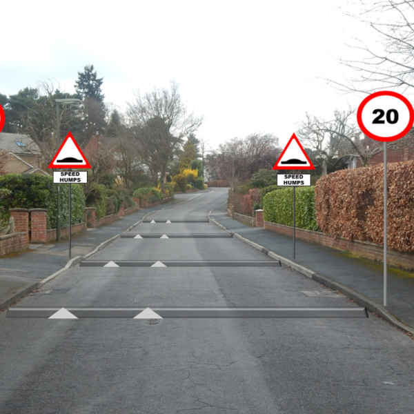
The British have done a whole lot of research into speed cushions specifically for use on their 20 mph zones. They have very specific design parameters for their speed cushions, in terms of the width of the cushion, the width of the gaps between them, and their spacing. They’ve also done studies that show that fire engines have no problem driving through speed cushions and maintaining speeds of 20-25 mph, but on the other hand, they reduced passenger car speeds to 15-20 mph.
Speed cushions are best used on fire response corridors, bus transit routes that have frequent bus service on them, and on local residential streets where emergency vehicle response time is kind of a big deal. It’s the only real way to reduce speeds on public roads without also impeding the ability of those emergency services to do their jobs.
Speed tables are flat-topped versions of speed humps, also called trapezoidal humps, plateaus or raised crosswalks. The primary difference is that the entire vehicle wheelbase rides on the elevated section rather than a peak where the vehicle body pitches up and down during the traversal. To maximise driver comfort, speed tables generally have a total travel length at least four times that of speed humps. Most agencies follow Institute of Transportation Engineers guidelines which use 3 to 3.5 inches (76-90 mm) high and a total travel length of 22 feet (6.7 m), 10 feet (3.1 m) of flat plateau with 6 foot (1.8 m) approach and departure ramps on both sides (Figure 1). Although these could be straight as per the ITE guideline, many agencies use either a parabolic or sinusoidal profile for approach and departure ramps. The difference in the geometry of the ramp produces a different ride, and there have been studies which have looked at quantifying the speed reduction and ride quality for different ramp geometries.
The longer travel length fundamentally changes the vehicle dynamics when compared to a hump. As the vehicle climbs the approach ramp, the front suspension compresses and the vehicle body pitches upward (Figures 2a and 2b). However, before the rear wheels encounter the approach ramp, the front wheels are on the flat plateau and the front suspension extends (Figures 2c and 2d). The result is a moment where the entire vehicle is sitting on a flat surface with a pitch angle near zero degrees. The rise time and pitch angle will be shorter and higher on a sinusoidal hump than a parabolic hump. The physics of speed tables produce a much gentler ride when compared to speed humps, since vehicles experience two separate instances of vertical acceleration (accelerating and decelerating) with a relatively large distance of level travel between them. Several studies have shown that this profile allows vehicles to comfortably cross speed tables at 20-25 mph (32-40 km/h). The long travel distance makes them appropriate for roads with higher design speeds than one would generally use with speed humps.
The United Kingdom has some of the most prescriptive specifications when it comes to speed tables. It is covered in the Department for Transport’s Local Transport Note 1/07. In 20 mph speed zones, the plateau may be formed by ramps rising 75 mm at a gradient of 1-in-12 (around 8.3 %). The plateau is usually 7 metres long for normal applications, but for public transport routes, the plateau is 12 metres long and a more gentle gradient of 1-in-15 (around 6.7%) is used to minimise the discomfort for bus passengers. A lot of thought has gone into the ramp gradient and plateau length in correlation with vehicle speed as is evident from the TRL Report 186 (Figure 3) which gives useful data on the subject.
UK Design Standards – TRL Report 186
The study measured the speed of motor vehicles on roads with speed tables and between speed tables. The findings of the study were interesting. Speed tables were found to reduce speeds down to 13 mph (21 km/h), with speed between tables increasing to 20 mph (32 km/h) when spaced 84 metres apart (Figure 4). This clearly shows the importance of good spacing if you want to have a lower speed for a longer stretch of road. It also goes on to estimate that accident reduction is 44 % with vertical deflection treatments. The costs of these treatments are estimated at £10k per installation.
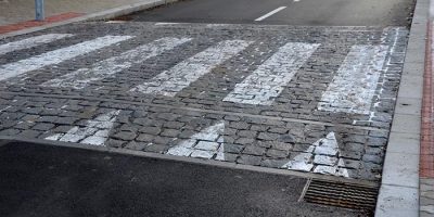
Speed tables have found use all across the road network. The main use is as raised pedestrian crosswalks, where the entire crosswalk is elevated to pavement level. This reduces the step down to the pavement, and in addition to making it more visible to drivers, also requires less effort for pedestrians to cross.
Speed tables are also popular at junction treatments, where they both reduce speed and reinforce the presence of the junction. Another major use is as traffic calming devices on residential roads, where the long travel distance and flat plateau can allow design speeds of up to 35 mph in some applications. This can open up the use of traffic calming devices to collector roads and minor arterials where speed humps would be inappropriate.
Speed tables are preferred over speed humps by drivers with disabilities and wheelchair users, as the flat top and more gradual approach ramps create less jarring motion. When used as raised crosswalks, they also create a truly level crossing surface for pedestrians by eliminating the need for a kerb ramp, making them a boon for people using pushchairs or wheeled luggage.
Comparative Vehicle Dynamics and Physics
The physics of speed deflection is simple. When a vehicle hits a raised surface, the wheels follow the shape of that raised surface. The vehicle body, meanwhile, has a natural period of vertical motion which doesn’t change as quickly. This is what creates the vertical acceleration and jarring which we have already discussed. So, to recap, there are three main factors that determine the severity of the vertical acceleration during the traversal of a bump:
1. Height of deflection
2. Length of deflection (approach angle)
3. Vehicle speed
The relationship between these three factors is exponential. Doubling the speed on a given bump geometry will cause more than double the vertical acceleration. This exponential increase in vertical acceleration is the enforcement mechanism that makes vertical deflection work. We saw this in the case of vertical acceleration, which quadruples or more with each doubling of speed over a given bump. That’s why speed deflection only works properly when vehicles slow down to an appropriate speed for the given geometry.
It is important to point out that speed reduction is both a requirement and an outcome of good vertical deflection design. It is an outcome, since any traffic calming device that causes a driver to slow down is going to make vehicles more compliant with the design speed of that device. But it is also a requirement, since a device will be ineffective if the traffic exceeds its design speed. This is why speed bumps are so poorly suited for through-streets – drivers will only hit the speed bumps with an acceptable speed if they are going to the same parking lot at 3am. This requirement for speed reduction is why properly engineered vertical deflection is such a valuable traffic calming tool.
If you recall from our earlier section on physics, the exact point of maximum vertical acceleration during bump traversal is during the first half of the bump where the wheels first strike the rising vertical surface. At this point, the suspension must immediately compress to absorb the vertical displacement. The vehicle speed sets the maximum rate at which the wheels rise, but the spring rate and damping set the maximum rate of suspension compression. Even the softest luxury sedan suspension has limits to how fast it can compress. If the vehicle speed exceeds the design speed for a particular speed hump, then the suspension will bottom out on the hard stop before the rise angle has finished. The result is a hard stop as the chassis slams into the frame and that force is transferred to the driver and passengers.
Vehicle suspension characteristics are a key piece of the puzzle in determining how a particular vehicle will respond to a speed deflection device. The softer the suspension and the longer the travel distance, the more deflection a suspension system can absorb. This is why top-of-the-line luxury sedans generally fair much better than stiffer sports cars on aggressive speed humps. But even luxury sedans will exhibit significant discomfort when speed deflection devices are encountered at the wrong speed. The reason is simple: the suspension can only absorb so much of the vertical deflection before the hard stop of the chassis reaches the frame.
Something that is often overlooked in the discussion of speed deflection devices is how they affect tyre-road adhesion. A recent study demonstrated that wheel surface adhesion index (WSAI) or a measure of how well the tyre can grip the road surface drops significantly with the more aggressive speed bump profiles. Flat topped bumps were found to reduce the adhesion index down to around 0.6, while sinusoidal profiles kept the adhesion index around 0.85. A reduced tyre-road adhesion affects vehicle control and this can be particularly problematic during braking or cornering immediately after the bump. This is one of the reasons why speed humps should not be placed on curves or immediately before intersections or other areas where drivers need to stop suddenly.
The ultimate enforcement mechanism is driver and occupant discomfort. Occupant discomfort manifests as vertical acceleration which the vestibular system in the human ear senses as unpleasant and jarring motion. A body of human research on vertical acceleration tolerance has found that sustained accelerations above 0.3 g (3 m/s2) are deemed uncomfortable, while peak accelerations in excess of 0.5 g (5 m/s2) are distinctly unpleasant. We know that speeds bumps can exceed peak vertical accelerations of 1.0 g if traversed at high speeds, while properly designed speed humps and tables keep peak acceleration below 0.5 g at the design speed.
Conclusion
The traffic calming effectiveness of vertical deflection devices is directly related to how much the travel distance deviates from the 1:1 rule. The harsher the deflection, the more jarring the ride. On the far end of the spectrum, we have speed bumps with their very aggressive deflection profile which make vehicles pitch and dip sharply. Speed humps are slightly less aggressive with a 1: 3 deflection ratio (eight inches high and 24 inches long), and have a standardised design that can be very effective at reducing speeds when implemented at an appropriate target speed. Speed cushions offer a useful middle ground on emergency response routes, since their design still effectively reduces speed on passenger cars but their narrow middle section allows wide-track vehicles to pass over without pitching or waiting for response units to pass. Speed tables are the most refined option in this category, providing traffic calming while maintaining driver comfort and providing excellent integration with pedestrian crossings.
There is a convergence of the UK speed table standards and international guidelines. The former’s more detailed design standards, backed by research from the Transport Research Laboratory, is a demonstration that these devices can meet the appropriate targets for speed reduction with an expected accident reduction of 44 %, while maintaining good levels of driver comfort and ensuring emergency vehicle access. It is a welcome development that North American agencies are also being provided with detailed design guidance by ITE, AASHTO and FHWA to aid their efforts. It is important that these agencies adhere to these design standards. Failure to do so is a recipe for the implementation of vertical deflection devices that are either ineffective at enforcing desired speeds or which are so aggressive that they damage vehicles, make the drivers uncomfortable and create liability issues. The design of these devices should be a balancing act where the traffic engineer and local authority needs to carefully consider the specific requirements of the location – existing speed, target speed, traffic volumes, vehicle mix, emergency access requirements, pedestrian activity and so on. Careful site analysis and following proven engineering standards will help achieve the purpose of vertical deflection devices in creating safe streets for all road users.
Vertical deflection devices are a proven, cost effective way of managing vehicle speeds on roads where traditional enforcement strategies are impractical or just too costly to maintain. Vertical deflection devices are self-enforcing since they rely on the fundamental physics of vertical acceleration and the built-in human discomfort threshold to create a speed limit which is always ‘on’. As our cities continue to densify and the vision zero targets for road safety come into sharp focus, the more sophisticated application of speed humps, cushions and tables, guided by evidence-based engineering standards and research will play an important role in creating safer streets.